Time for a Home Lab upgrade! I wanted to neaten up some of my cabling, move some devices for better cooling, and add some Raspberry Pis which had become spare. Also, after watching Jeff Geerling’s mini-rack series, I got jealous and wanted my own 😂
Overview
First lets run through the result, and then look at the build in more detail.
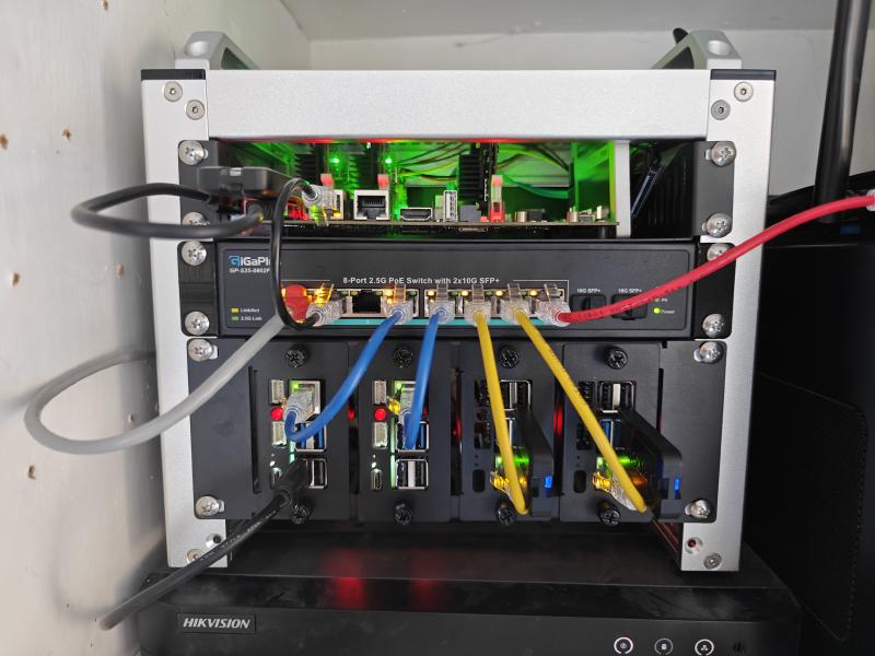
Working from top to bottom, left to right, the rack contains:
- A Turing Pi with 3 Raspberry Pi Compute Module 4 (CM4) nodes
- A GigaPlus PoE+ network switch
- A Rack Mount with NVMe boards for Raspberry Pis. In the rack mount are:
This is all enclosed in DeskPi RackMate T0 10 inch 4U mini-rack.
The only power supplies are to the network switch and the Turing Pi. Everything else is using Power over Ethernet (PoE) which removes a number of cables and makes things much neater.
The Build
Chassis
The rack size was restricted a little by the size of the cupboard it was going in*. I could buy a bigger rack and modify the cupboard for it to fit, but I determined I could probably** get everything to fit in a 4U rack. So I went for the DeskPi RackMate T0 - 10" 4U Mini Server Rack.
Assembly of this was fairly straightforward. I was a little surprised to find that you can add fans into the bottom. This didn’t seem to be listed on the product page or wiki, but is in the instructions. For some reason it doesn’t include size information either, but I believe two 80mm fans would fit.
*The front of the cupboard has been modified to include 2 fans acting as an intake and exhaust to improve cooling.
**Uncertainty of it fitting will be covered in the Turing Pi section.
Raspberry Pi Rack Mount
We’ll start at the bottom with the 2U 10" Rack Mount with 4x PCIe NVMe Boards for DeskPi RackMate. The plan here was for:
- 2
Raspberry Pi 5s (Pi5), each using:
- A Corsair 500GB NVMe drive for storage
- A Waveshare PoE hat (G) for power
- 2
Raspberry Pi 4s (Pi4)
- A Corsair GTX USB drive for storage
- A Waveshare PoE hat (E) for power
Raspberry Pi 5s
The first Pi5 was fairly straightforward. It was already running HA OS, so it was a case of mounting the NVMe board to the base plate, the Pi on top, and the PoE hat on top of that. Then I had to move the OS from the USB drive it had been using previously, to the NVMe drive. I had forgotten to get a USB NVMe enclosure to do this, so had to boot Raspberry Pi OS on the device itself from another USB drive, then plug in the HA OS USB drive and transfer it to the NVMe. HA OS automatically resized on boot.
When I first booted the Raspberry Pi using the NVMe or PoE board for power, it would not boot. These boards supply power directly to the GPIO pin headers, and as a result, the Raspberry Pi seems unable to determine how much power is available. In order to prevent issues resulting from trying to draw more power than is available for things such as USB devices, the Pi refuses to boot without pushing the power button. Given there is plenty of power available through the PoE hats, the fix is quite simple. I just had to add the line usb_max_current_enable=1 to the /boot/firmware/config.txt file. I also added dtparam=pciex1_gen=3 to enable PCI Gen3 support for the NVMe drive.
The next Pi5 was a little different. The hardware setup would be the same, but it was being repurposed from elsewhere, and would be running Raspberry Pi OS Lite, and be running
K3s to become part of my Kubernetes cluster. This was going to replace a Pi4 which had been running a secondary DNS server on my network, and eventually it will take over the AI workload. For now though, booted Raspberry Pi OS from a USB, and then used the Raspberry Pi Imager to prepare the NVMe. After making the same config.txt changes as the first Pi, I rebooted, and then applied my Ansible playbook for my k3s nodes.
Raspberry Pi 4s
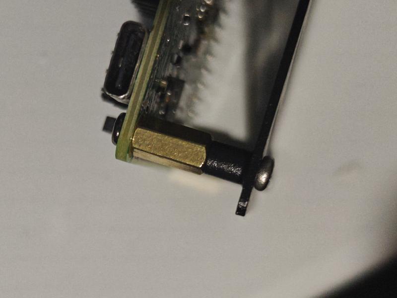
The two Pi4s presented with some hardware difficulty. All of the PoE hats arrived with only female-female type standoffs. In order to attach the PoE hats for the Pi5s, I had used the standoffs from the other NVMe boards. After some time frustrated at having to buy more standoffs, I came up with a workaround. The holes for the standoffs in the base plate go all the way through, and the PoE hats include some longer screws. By putting the screws through the bottom of the board instead of the top, they poke out by about 2mm. The female-female standoffs can then attach to the ends of the screws. These standoffs are slightly longer than the NVMe board standoffs, so the ports on the Raspberry Pis happen to line up perfectly with the face plate.
From here, the setup of the Pi4s were straighforward. They would each be running from a
Corsair GTX which I now had spare, so could be setup using the Raspberry Pi Imager from a laptop, adding the usb_max_current_enable=1 setting, and then again applying the Ansible playbook to configure them as K3s nodes.
Turing Pi
Next we will jump to the top of the rack, for reasons which will become apparent.
The Turing Pi was to be moved from another room where it sat in a Mini-ITX case. The CM4s running here had a tendency to run hot and thermal throttle. They had heatsinks, but no active cooling. Hopefully this move would allow better airflow.
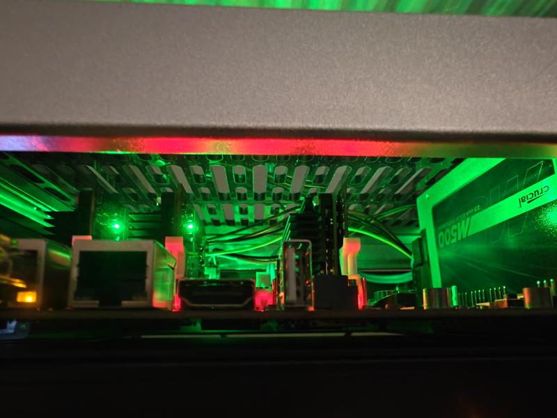
I had bought the ITX mounting shelf and mounted the Turing Pi to it. I had forgotten in the planning that one of the nodes had an SSD attached to it. After mounting the Turing Pi, I noticed some holes around the edge of where the board was mounted. I have no idea if this is their intended use, but they are perfectly placed for the SSD mounting holes. Even without the SSD, the Turing Pi would take up more than 1U of space. Handily, there is a bit of space in the top of the rack. The CM4 nodes still have a little space between the top of the adapter board and the top of the rack, while the SSD touches the top and is still angled slightly (It isn’t being pushed over, the sides of the SSD are angled slightly so it naturally sits like this, but it is also touching).
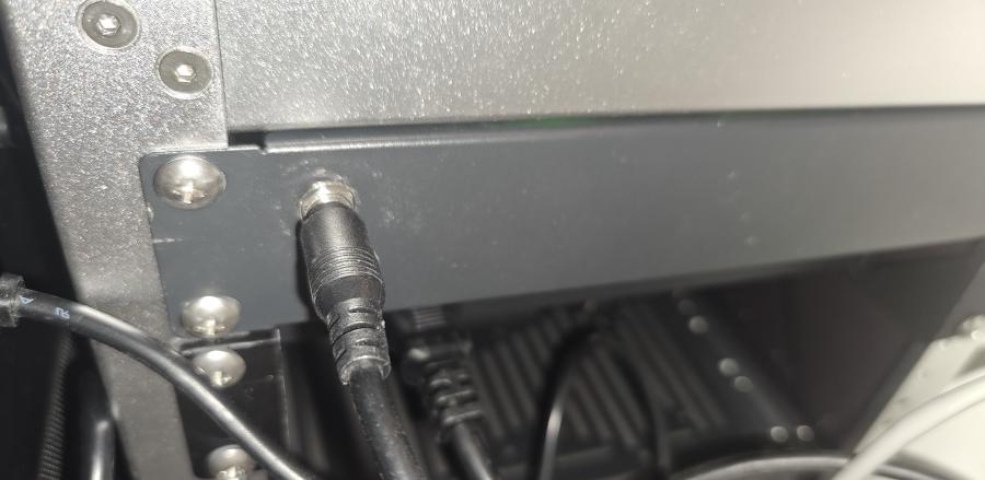
With the Turing Pi attached, it had to be put into the rack lower down, and then moved up into the top position. I then drilled a hole in the blanking plate supplied with the rack chassis, and mounted it on the rear as the power port for the pico-PSU of the Turing Pi.
Network
The final component is the network switch. The main requirement here was I wanted it to support PoE at full power for the 4 Pi nodes. I selected the GigaPlus from the list at Jeff’s mini-rack page. It also has 2 SFP ports which I may play with at some point. The switch is then mounted using the 3D printed rack ears mentioned on that same page.
I typically try to use red boots for any critical network connections between switches, routers, and access points. I will sometimes use some colour coding, but it tends to be specific to where the cables are. The cables are coloured in this case but stick to a similar scheme: red are for network critical, black is for the Turing Pi, blue is for the Pi5s, and yellow for the Pi4s.
Conclusion
So was it worth it? Well…
- The “Server Cupboard” has fewer cables and looks much neater
- It is much easier to temporarily move things to a different room
- The Turing Pi has been moved freeing up valuable shelf space
- The nodes within the Turing Pi run about 10 degrees cooler and aren’t thermal throttling
- My Kubernetes cluster is upgraded with:
- 2 more nodes, one of which is a Pi 5 which should vastly increase performance and stability
- Increased storage volume capacity within the cluster
- I gained new knowledge about:
- PoE
- NVMe on Raspberry Pi
- USB power limitations on Raspberry Pi
- I have improved/added learning platforms for future use (Kubernetes and Fibre Networking)
…but most of all, it was fun!


